Poor man’s indoor pool Link to heading
So, my house has a basement. And where I live? It rains. Actually, when it rains, it pours, and when that happens, well, my basement apparently moonlights as an indoor swimming pool.
Now, my basement does have a sort of rain collection system – you know, like many houses, it has a pit (sump pit, for the fancy folks) with a submersible pump. This pump is supposed to trigger automatically with a little floaty thing (a buoy!) when the water in said pit gets high enough. I definitely didn’t install it, which is probably obvious because whoever did clearly didn’t think the pit should be, oh, I don’t know, deep enough to actually let the water rise and trigger the pump before it starts auditioning for “Waterworld” all over my floor. But no, this pit is so shallow that by the time the buoy would even think about triggering, I’d already be wading in knee-deep water.
This is one of those problems that, when it arises, feels like the absolute worst thing that could possibly happen (an impromptu Olympic-sized pool in your basement is rarely ideal). But, it’s such a sneaky seasonal issue that you totally forget about its treachery… until the next torrential downpour. Then, it’s a mad dash to the basement to manually switch on the pump, all while cursing the many, many dry days you could have fixed it but, alas, did not.
But no more, I say! Today, we banish the basement bog! Today, we fix this soggy saga… with tech!
Of course its an Arduino project Link to heading
What did you expect? Sure, this is a problem that could be solved with a shovel and some good old-fashioned manual labor (i.e., digging a deeper hole). But where’s the fun in that? Nope, we’re bringing in the microcontrollers – the go-to tech for both certified geniuses and, let’s be honest, anyone who thinks a ‘smart q-tip’ (the iOtitis) is a groundbreaking idea!
So, first question: What should my glorious new solution actually do? I’m a big fan of simplicity, and the pump’s existing design is beautifully basic: a buoy rises and falls with the water level, acting like a simple on/off switch. Perfect! That means I can replicate that core logic with something equally straightforward: a relay.
Crucially, I don’t want to mess with or damage the pump itself. So, the original buoy will stay. I’ll just fix it in its ‘always on’ position (or effectively bypass it) and then control the pump’s power using my new relay, spliced into the power cable that plugs into the wall socket.
Second challenge: How do I actually detect the water level? My first thought went to those little Arduino water level sensors – you know the ones with the exposed traces? But they’re pretty tiny, and I need to measure a range of about 5 to 30 cm. What about a pressure sensor? Nah, those are usually designed for much greater depths, making them too bulky and expensive for this humble project.
Enter the hero: the distance sensor! More specifically, an ultrasonic distance sensor. These bad boys are dirt cheap, super common, and incredibly well-documented. Winner!
Selecting the board Link to heading
Ah, the brains of the operation! The central nervous system, poised for such raw data-crushing and powerful computing tasks as… repeatedly requesting a value from the sensor, determining if it falls within the 5 to 30 cm danger zone, and if so, flicking the pump on. If not, well, it does nothing. Dramatic, I know.
Yeah, it doesn’t exactly require a supercomputer, I’ll admit. For someone so obsessed with efficiency and squeezing every last drop of performance out of components, it almost pains me to use a microcontroller for such a trivial task. Almost. Because, you see, it’s cheap and easy – and those are two things I might love even more than hyper-efficiency.
My criteria were simple: small, cheap, and “good enough.” I didn’t need Wi-Fi or BLE (though, a tiny part of me now regrets not being able to get a notification when the pump kicks in – future upgrade, perhaps?). Initially, I considered an ESP32-C3. I spotted some on AliExpress that weren’t outrageously priced, but the delivery dates were so far out in the stratosphere, I was genuinely worried my old pal Procrastination would have declared victory and the board would just gather dust upon arrival.

Then, salvation! I found a fantastic local supplier – massive shout-out to Mauser for their awesome selection and great prices! They had the Seeed Studio XIAO RP2040.
Beyond its ridiculously small size which is perfect for tucking away, the RP2040 chip itself is powerful enough for this and much more, it has just enough GPIOs for my sensor and relay.
List of parts Link to heading
As I mentioned, Mauser has some seriously cool stuff, especially for us tinkerers. So, I ended up grabbing most of what I needed from them, supplemented by a few bits and bobs I already had lying around the workshop (aka, my “organized chaos” pile). Check out the full shopping list in the table below!
| Component | Quantity | Price (€) |
|---|---|---|
| XIAO RP2040 | 1 | 6.02 |
| HC-SR04 | 1 | 1.99 |
| 5V Relay Module (Arduino compatible) | 1 | 1.22 |
| Resistor (2.2kΩ 0.6W±1% ⌀2.5x6.8mm) | 20 | 1.71 |
| Resistor (1kΩ 0.6W±1% ⌀2.5x6.8mm) | 20 | 0.81 |
| Plastic electronics box (74x89x41mm) | 1 | 3.38 |
| Stripboard (72x95mm) | 2 | 1.69 |
So, for just €16.82, I think I snagged a pretty sweet deal on the main components! Right then, let’s dive into the schematics so I can show you how this master plan (hopefully) comes together.
Circuit schematics Link to heading
Alright, let’s talk circuit schematics! Now, look, I’m not an electronics engineer, nor do I claim to be (would I even want to be, really?). So, please, no nitpicking if these schematics aren’t perfectly “proper” or “up to ISO 9000-whatever standards.” I’m sharing this for the love of the game, folks!
This was my first real rodeo with any kind of CAD/circuit design software, but I find it genuinely interesting. I’d love to get good enough to design a slick, single PCB for this whole setup and get it professionally manufactured – how awesome would that be? I dove into KiCAD, and I must say, it feels like seriously pro-level software, even if my usage was decidedly “beginner-level.” But hey, it got the job done!
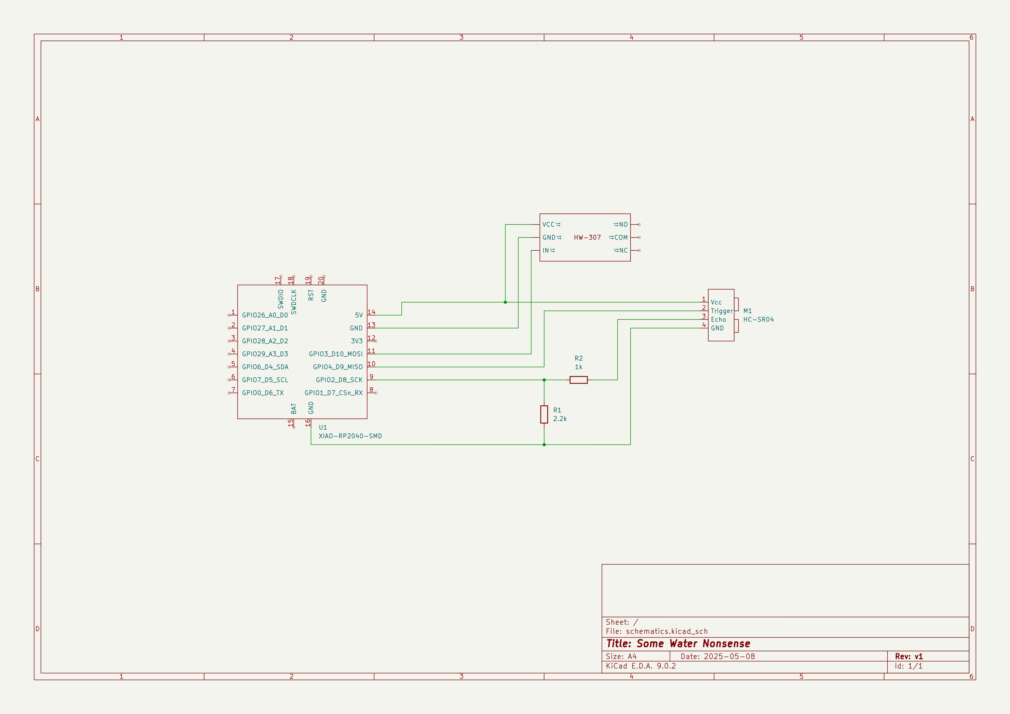
My circuit is pretty straightforward, with just a handful of main components. Initially, I thought the wiring would be even simpler, but a quick dive into the XIAO RP2040’s documentation revealed its 3.3V operating voltage. This meant I needed a voltage divider for the 5V sensor output to play nice with the microcontroller. Luckily, whipping one up with two resistors is super easy.
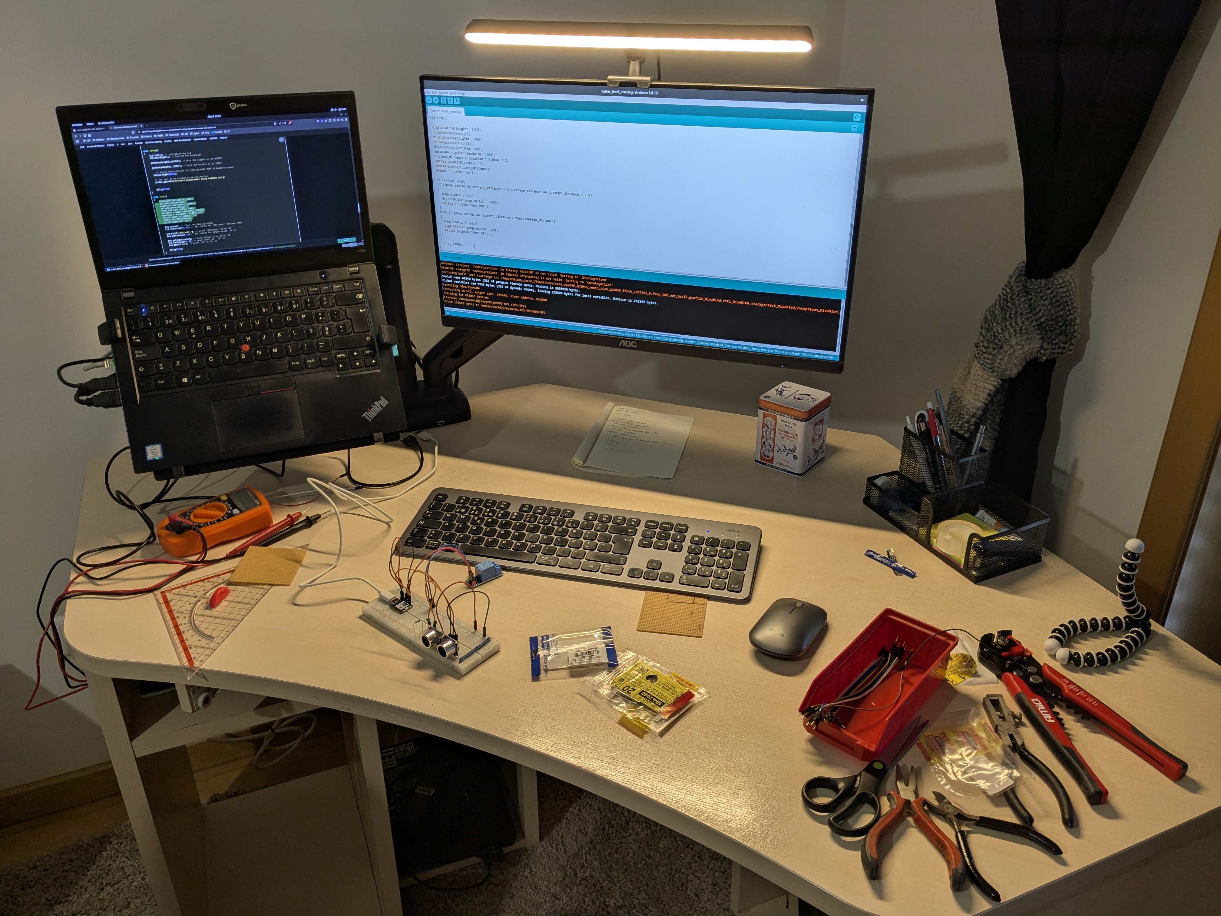
With the schematic sorted, I whipped up a proof-of-concept on a breadboard and – surprise, surprise – it actually worked! (Okay, maybe not a huge surprise, but still satisfying.)
I suck at soldering Link to heading
Then came soldering time. I remembered a blank perfboard I had stashed away and thought, “Perfect!” Oh, dear reader, HUGE mistake. A blank perfboard is a special kind of torture! No convenient strips, no helpful solder points – every single connection has to be painstakingly wired point-to-point with actual cable. Awful. Never again. Just use a stripboard, people… please, for your own sanity!
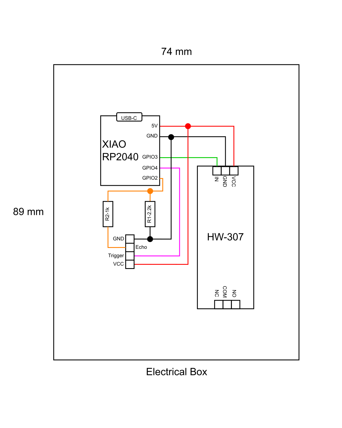
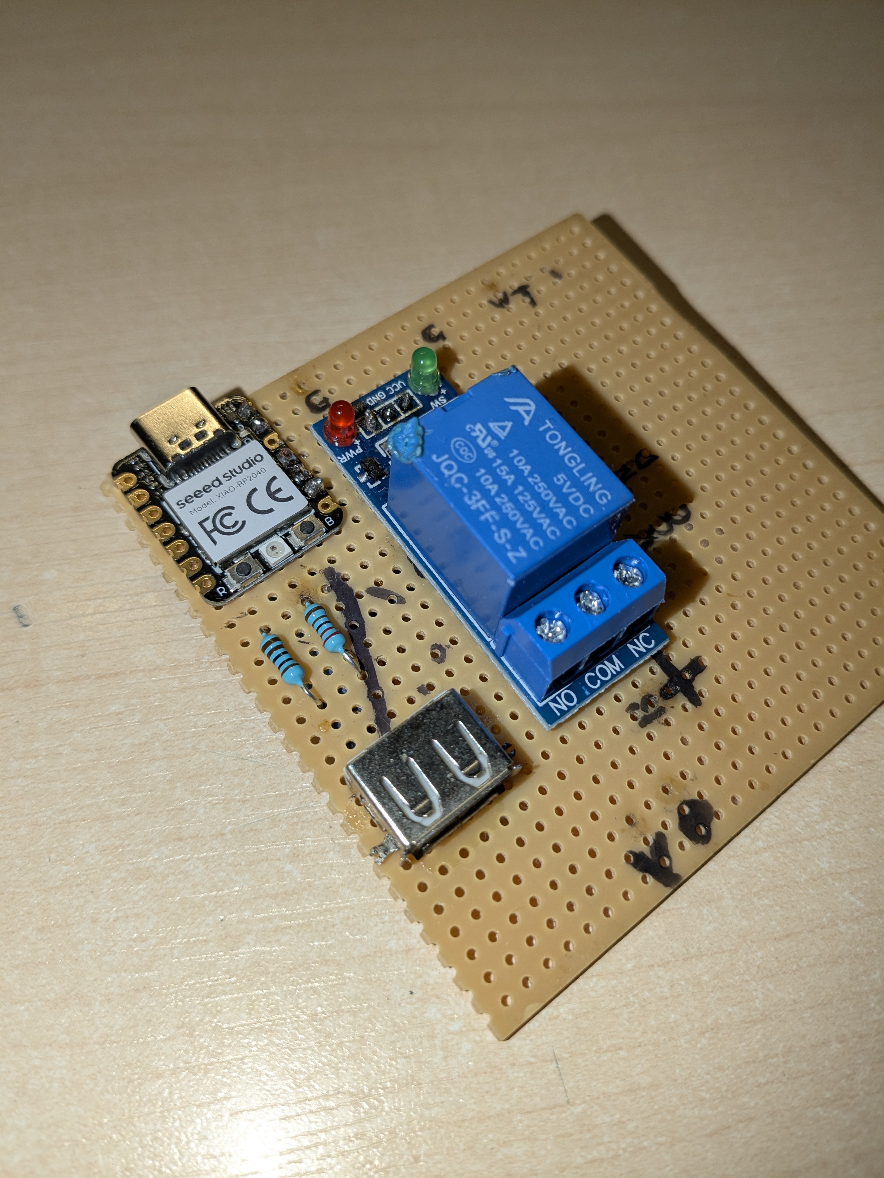
What didn’t help either is that I have approximately zero experience planning circuit layouts on a board. I sketched out a draft, as you can see below, and on paper, it looked like a masterpiece! Translating that to the tiny real estate of the board and actually soldering it? Yeah, that was a whole different ballgame, especially at such a small scale.
Now, look, I consider myself a multifaceted guy. By which I mean, I suck at a surprisingly large number of things, and soldering is definitely high on that list.
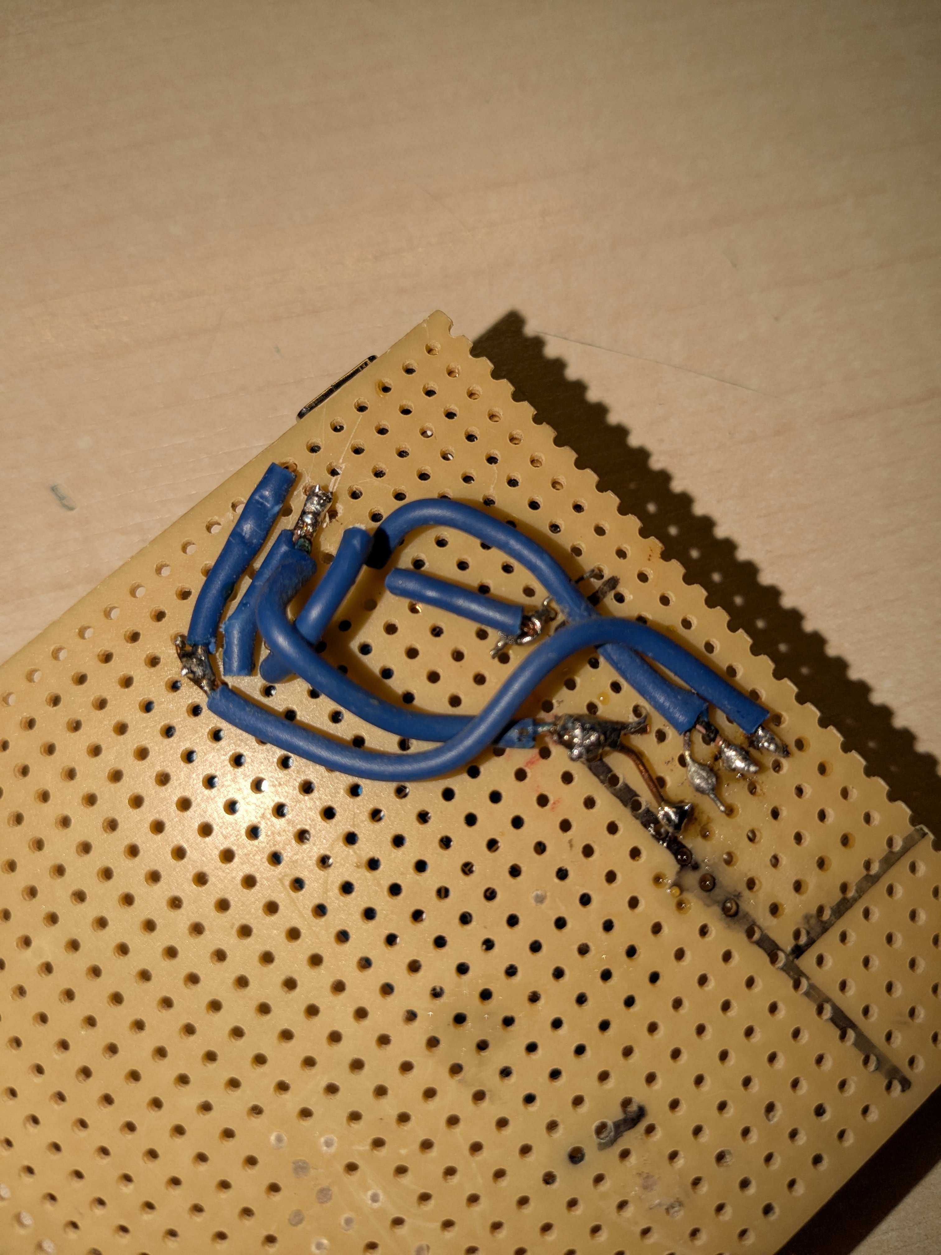
I began by placing the components on the board in roughly the positions I’d sketched in the diagram. I quickly discovered that “tiny components” + “short connections” = “a special kind of soldering hell.” But, I wrestled through it. Thankfully, I have a ton of solid core (monofilament) wire lying around, and it’s actually quite decent for this kind of point-to-point work.
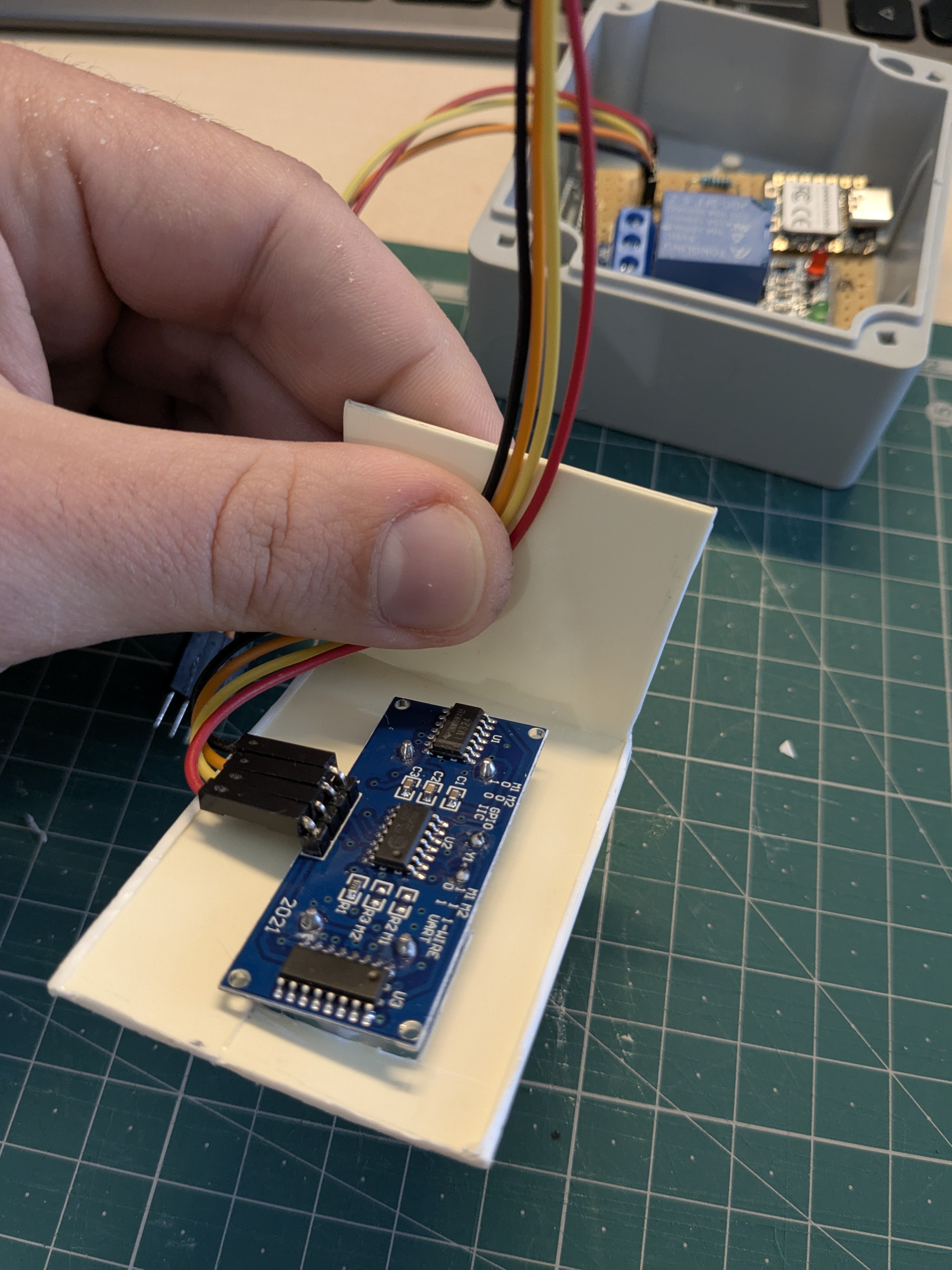
One thing I hadn’t initially considered was how to make the 4-pin connection to the sensor neat and tidy. But then, a lightbulb moment! I unearthed a female USB header from my glorious scrap bin. “Hang on,” I thought, “the sensor has 4 pins… a USB connector has 4 pins… could I just repurpose a USB cable for the sensor, creating a slick, easily connectable/disconnectable interface?”
The answer, my friends, was a resounding YES! In the immortal words of Jeremy Clarkson: “Sometimes my genius… it’s almost frightening.”
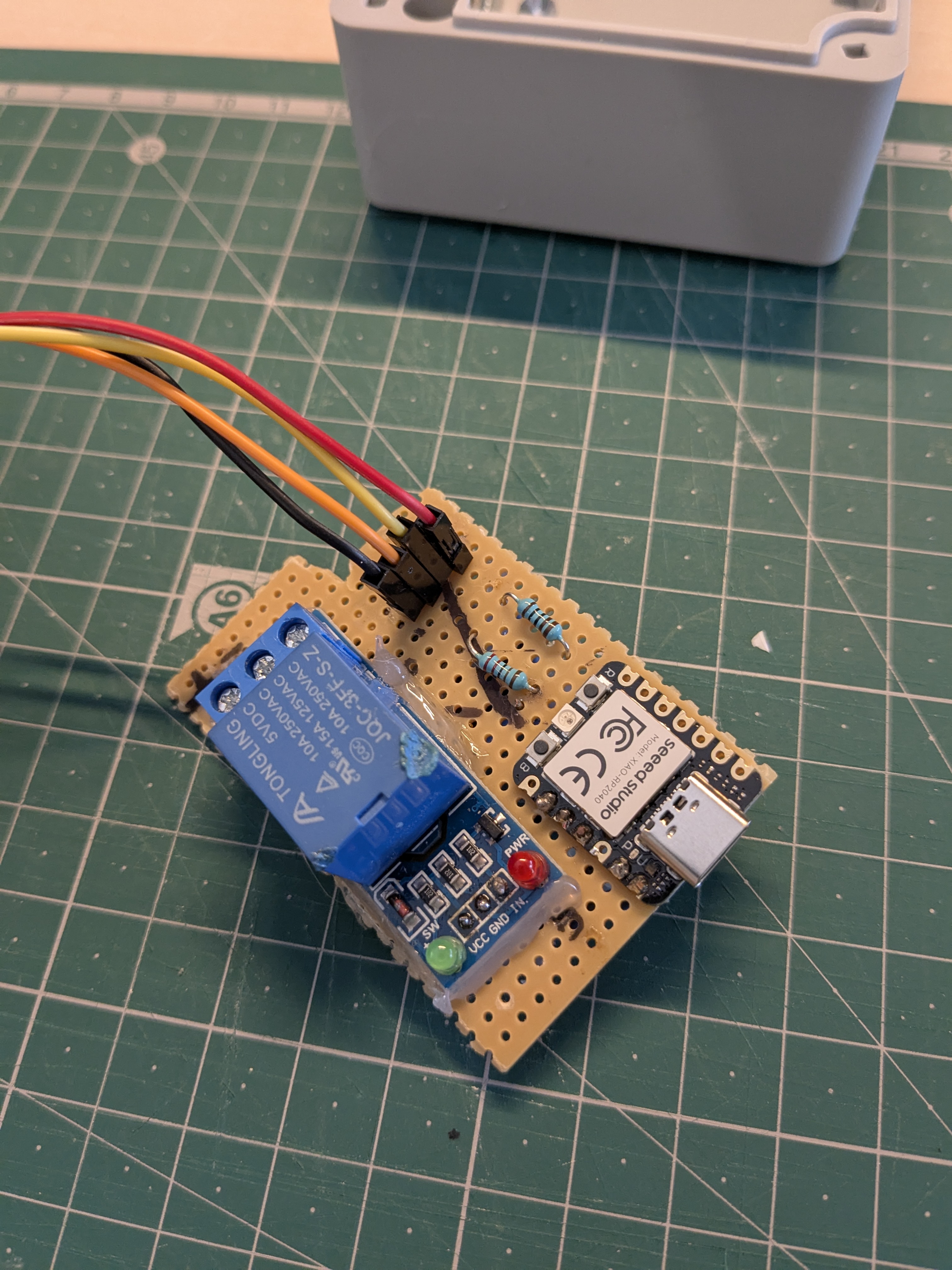
But then, disaster struck! The sacrificial USB cable I dug up must have been fossilized. It was so old and deteriorated that the internal wires were likely broken, because a continuity test revealed… absolutely nothing. Zilch. Nada.
Now, I’m a pretty frugal guy – I don’t like clutter if it’s not serving a purpose. Translation: I didn’t have another USB cable I was willing to sacrifice for this noble cause. (I know, I know, who doesn’t have a drawer overflowing with spare USB cables? Apparently, me!). So, I was faced with two options: buy a new USB cable, or rethink the interface.
Since my parts bin is generously stocked with spare jumper cables (the Dupont kind, perfect for easy connections!), I opted to make a custom 4-pin splitter cable with those instead. And you know what? It ended up working quite nicely.
Still, if you replicate this, definitely go for an adapted USB cable – it’s a cleaner solution.
Box it up and deploy it Link to heading
With everything (allegedly) working, it was time to wrap it all up in a neat little package.
I knew this contraption would end up lying on the basement floor, a veritable flood zone, so I wanted to protect it as much as humanly possible. That’s why I ordered one of those rugged electrical junction boxes – the kind that are airtight and designed to brave the great outdoors and all its elements.
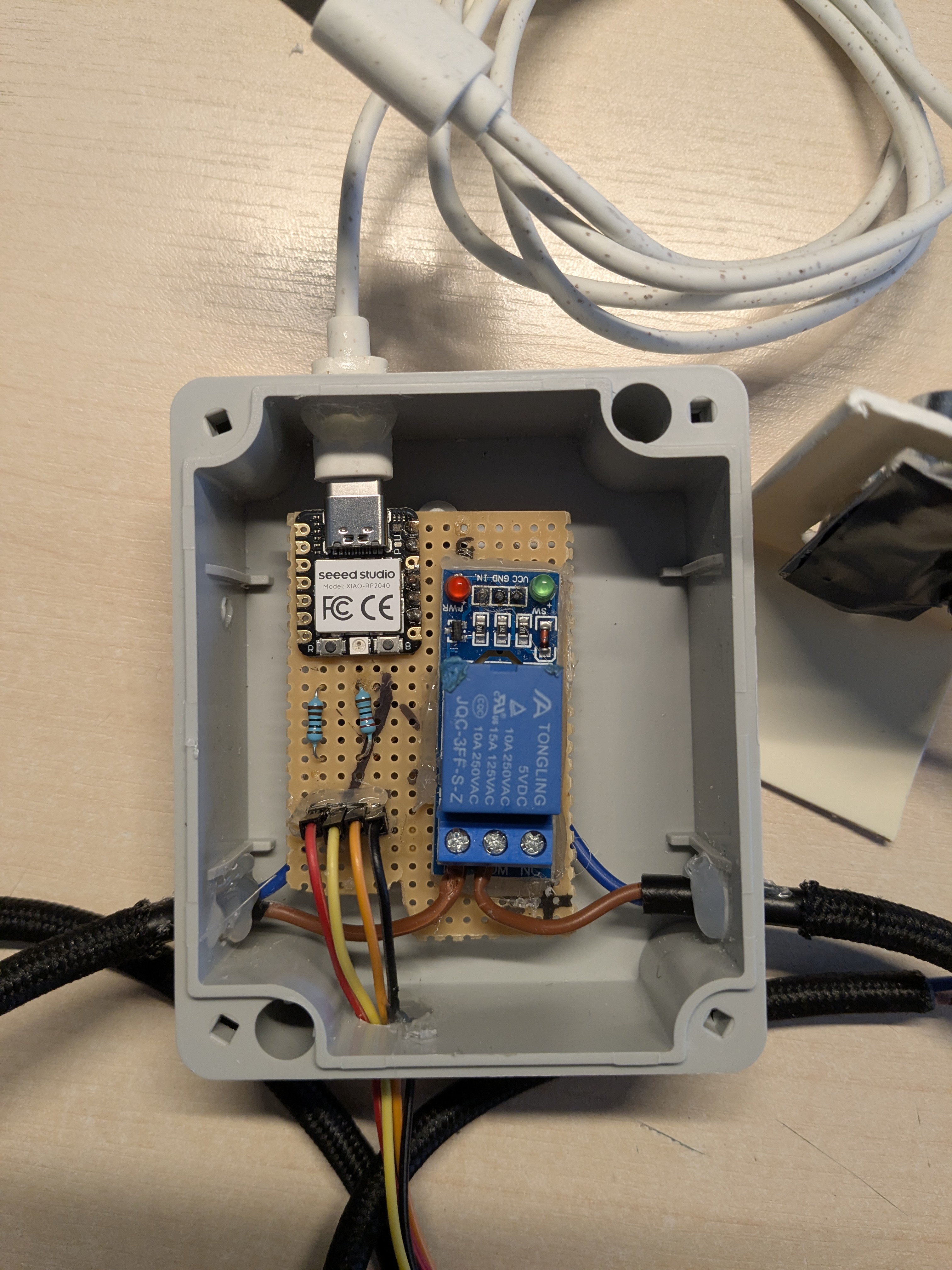
And I can definitely attest to their toughness; drilling the holes for the cables was a workout, but I managed! In this setup, as you can see, I also repurposed a beefy cable I had lying around, properly rated for the 240V circuits we have in our European homes. This became the lifeline connecting the pump to its power source, with my trusty relay playing gatekeeper for the electricity. Of course, hindsight being the perfect 20/20 it is, I really should have made that cable longer. Naturally, I ended up needing an extension cord to reach the wall socket. Oh well, that sounds suspiciously like a “Future-Me” problem.
I also meticulously sealed every cable entry point with a generous helping of hot glue – just in case any dirt, moisture, or adventurous insects decided my genius invention looked like prime real estate for a new home.
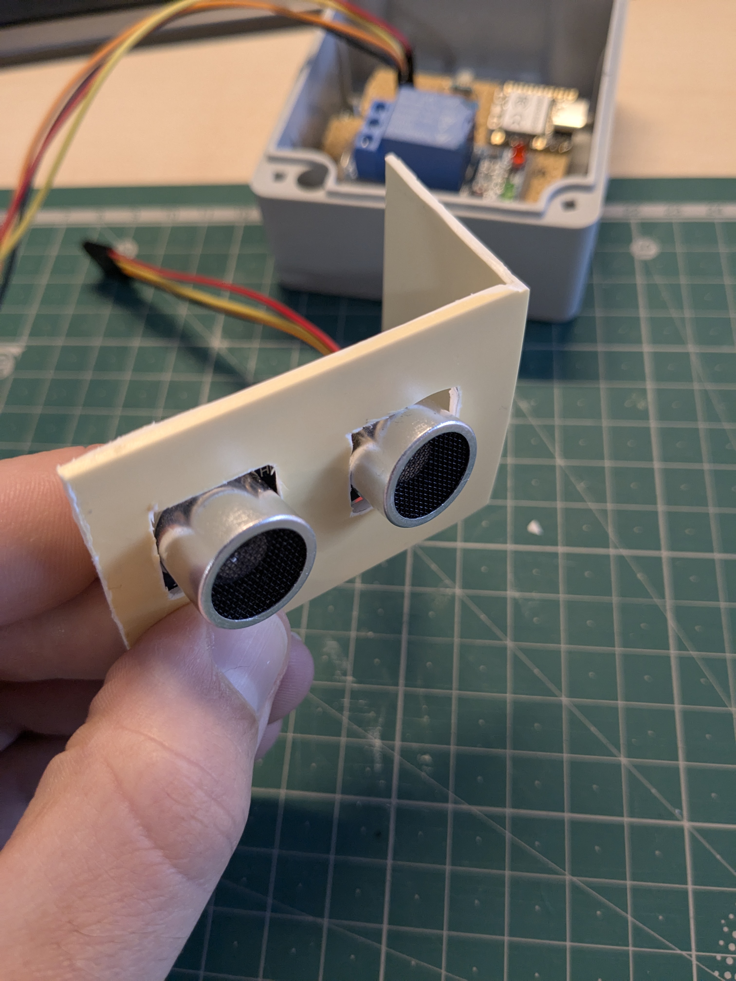
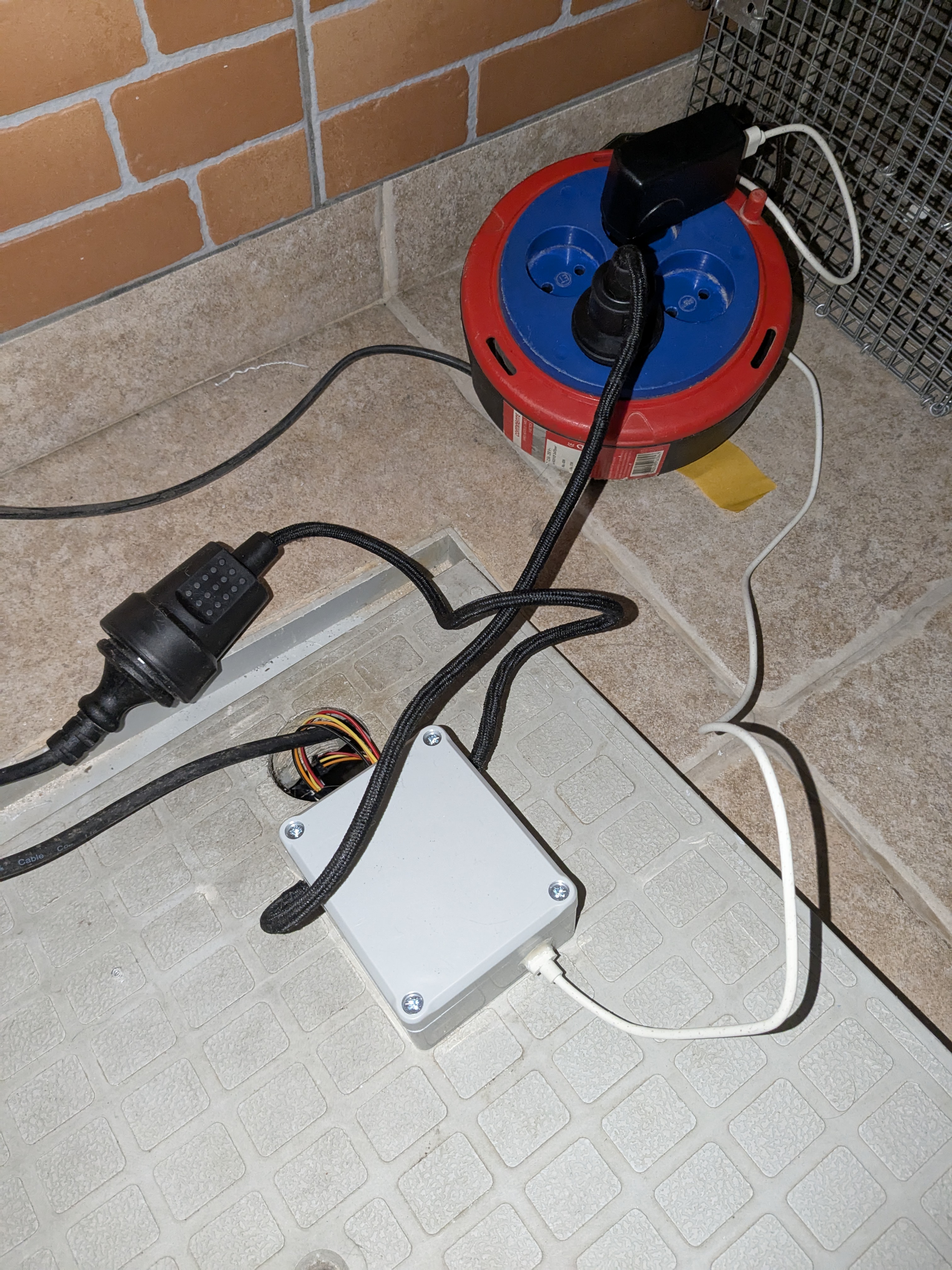
Deploying the sensor itself was surprisingly the easy part. The sump pit lid conveniently already had a hole for the pump’s power cable. So, I figured placing the sensor nearby would let me use a nice short cable (just two jumper cables long, in fact). I scavenged an old piece of plastic, fashioned it into a makeshift holder with a couple of strategically drilled holes, and zip-tied the sensor to it. A healthy application of double-sided tape, reinforced with a dollop of super glue for that “absolutely-no-way-this-is-coming-off” strength, secured it to the inside of the lid. I triple-checked that the lid could still close properly without dunking my precious handiwork into the watery abyss below.
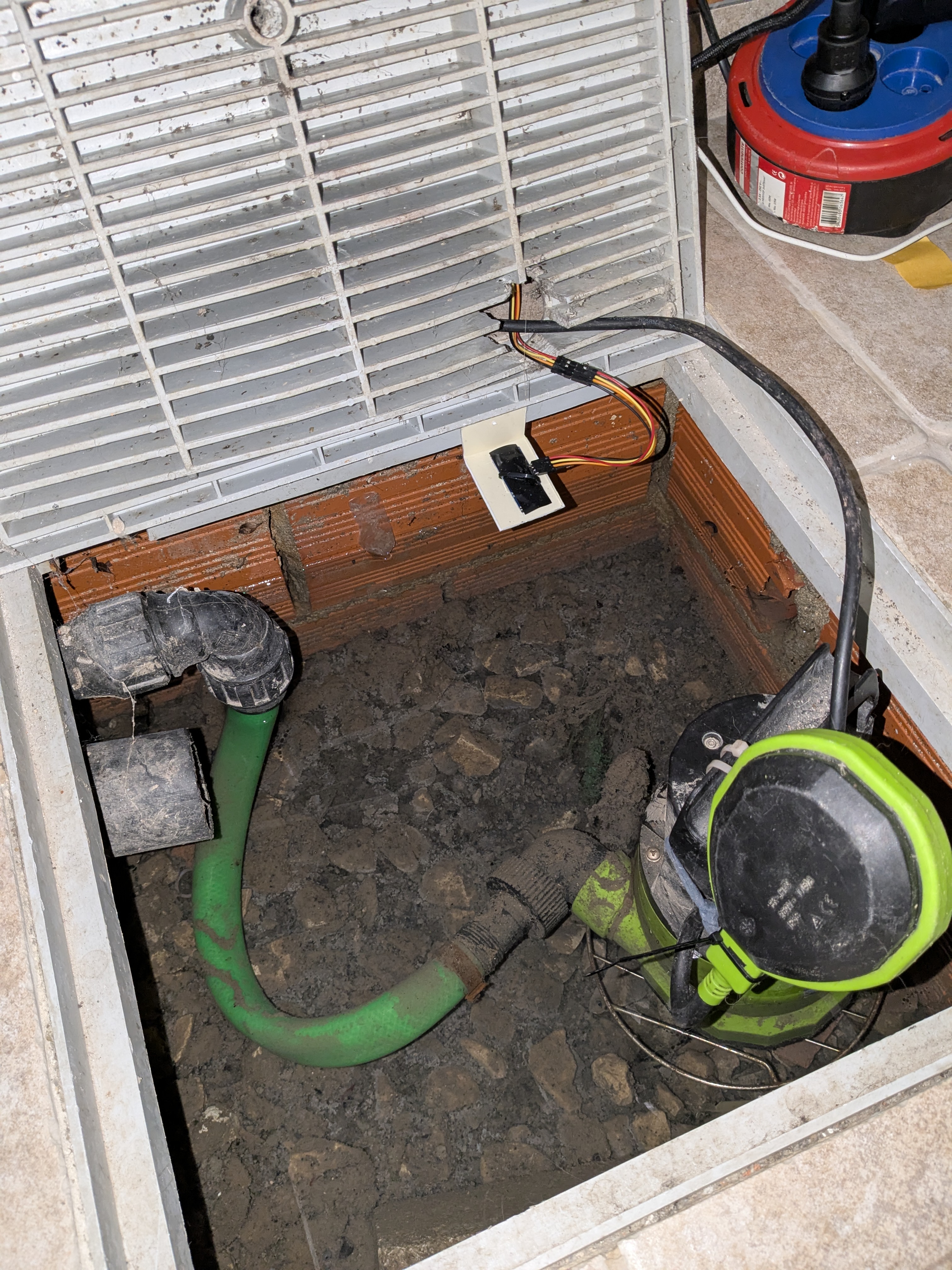
And as you can see from the deployed setup… there’s just one tiny, insignificant, almost unnoticeable problem: the pit is so ridiculously shallow that the top of the pump itself now prevents the lid from closing. Whoops.
So, in grand conclusion: despite my valiant, tech-fueled crusade to avoid manual labor at all costs, it turns out I still need to resort to good old-fashioned digging. I have to deepen that blasted hole so the lid can close, and I can finally pretend this whole saga never happened. Thus, manual labor proves itself inevitable, and I am forever defeated in my glorious quest for a victory of ingenuity over elbow grease. The irony is not lost on me.
Till next time folks, I’m gonna go look for a shovel…